


The St. Augustine Lighthouse Archaeological Maritime Program (LAMP) wants an ROV to scout out the ocean floor for potential shipwrecks, as well as orient their divers during the excavation process.
In order to save resources, a disused test platform based on AndyMark's RhinoTrack was selected as a starting point.
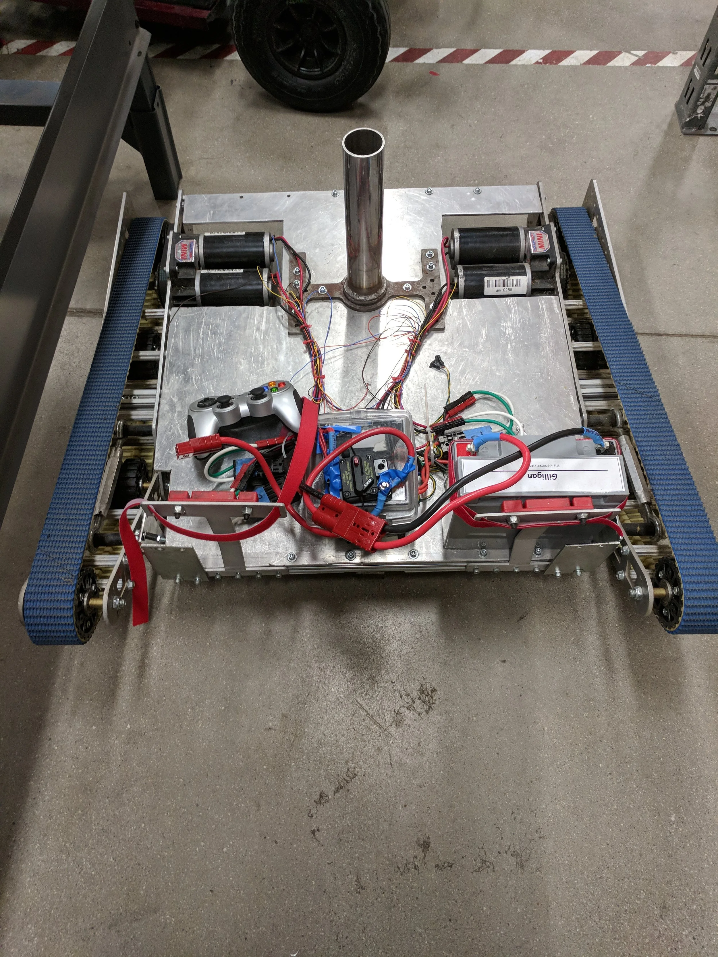
This is the base system that was retrofitted for underwater use.
Here the tread system mechanics can be clearly seen. There are many parts of this system that will later be replaced with corrosion resistant parts to handle both the abrasive sand and the saltwater that it will soon call home.
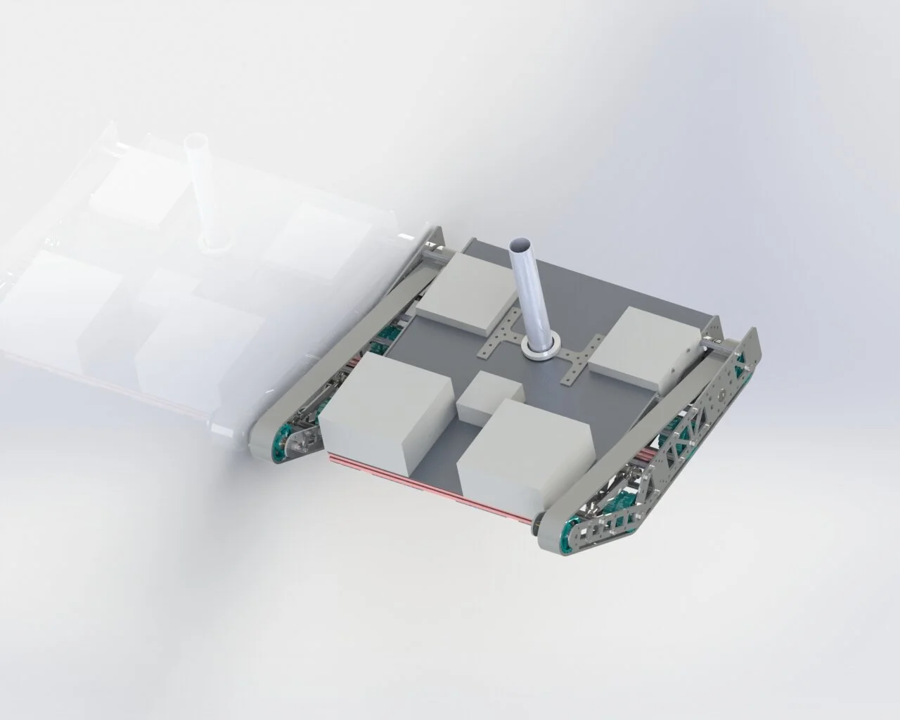
This is an early design concept. All of the boxes are separate with wires run between them sealed with bulkheads.
This design also featured batteries stored on the system for higher efficiency. This was soon phased out because of concerns with running time.
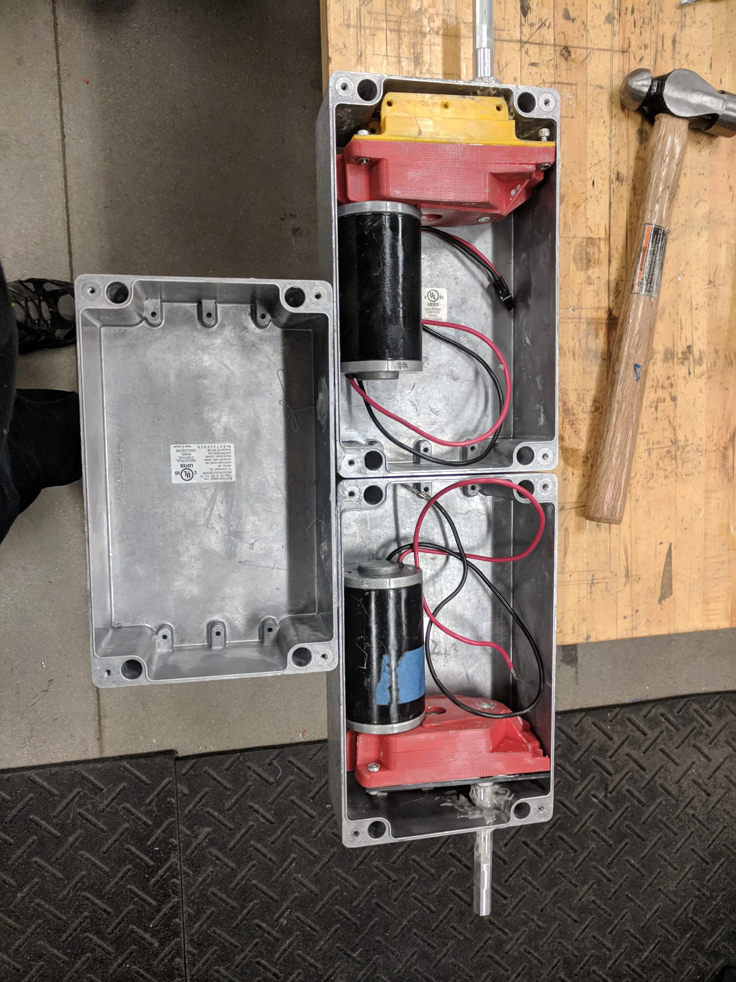
One of the first tasks in waterproofing this platform was to determine how the electronics were going to be sealed away. Design constraints did not allow for control boards to be potted in epoxy, therefore, several waterproof boxes were acquired.
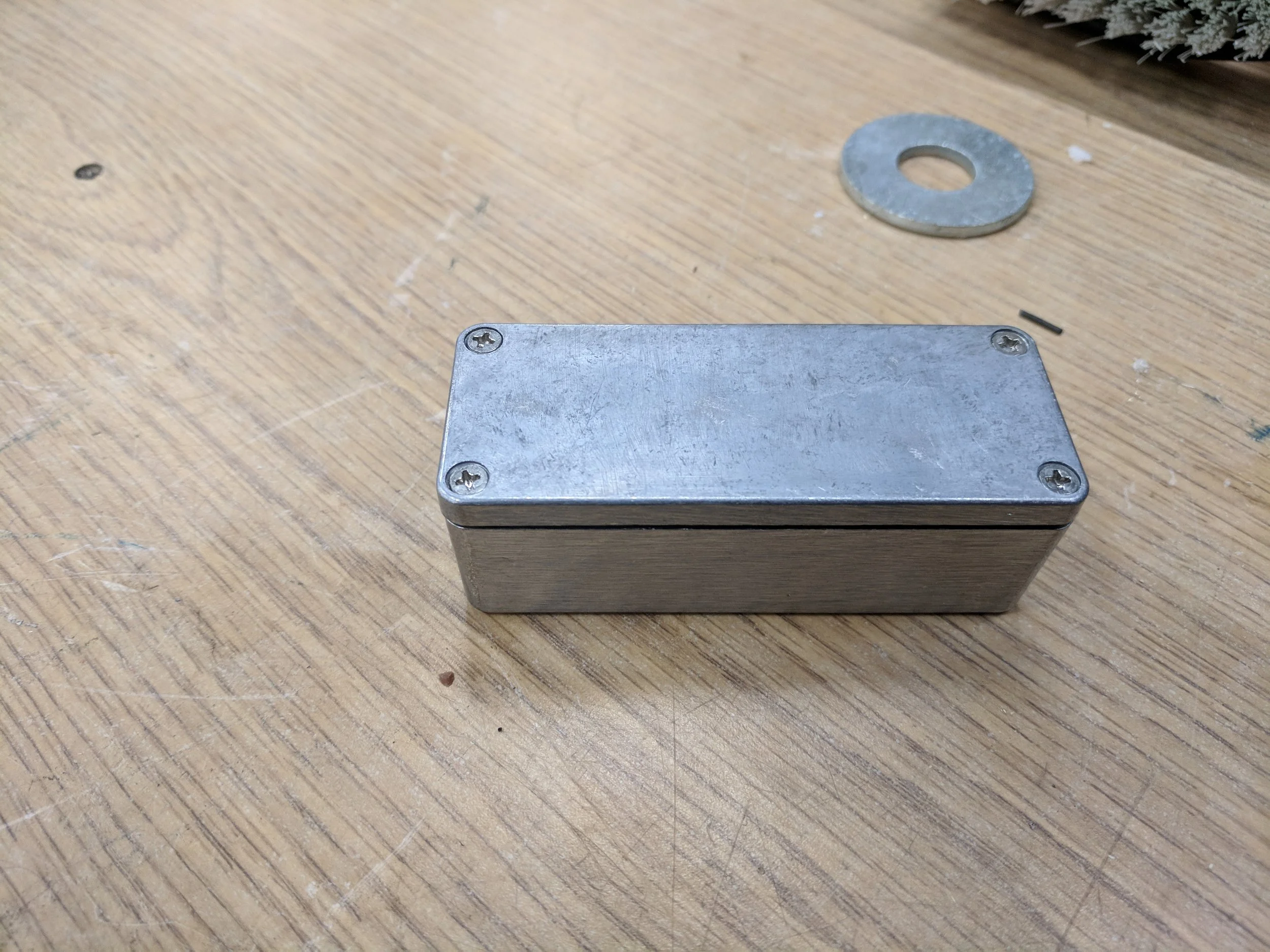
This is a standard electrical box that was also tested using the same methodology,except it was also filled with mineral oil in an attempt to slow down any leaks. However, this box is still not perfect.
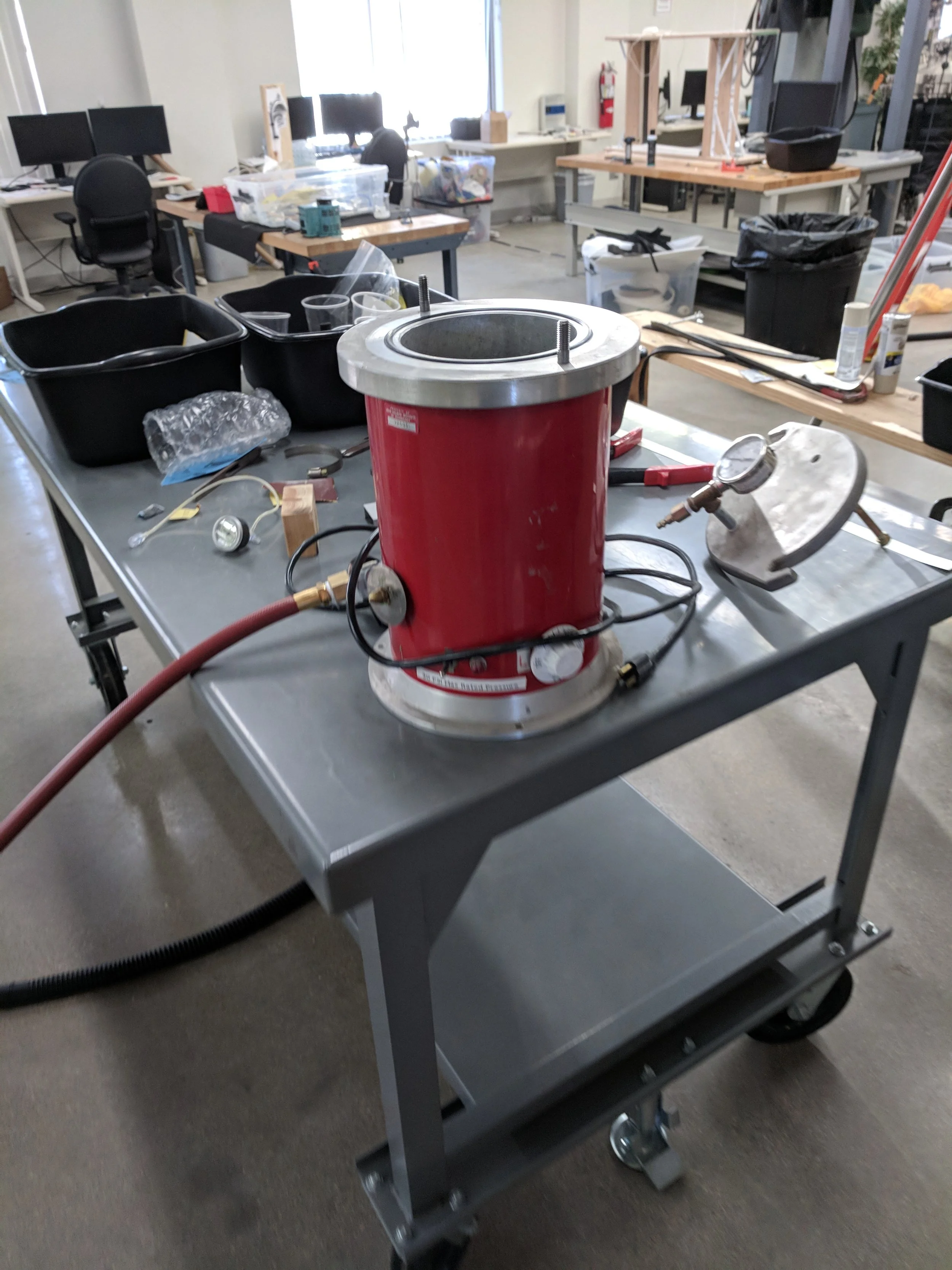
The ROV had to be able to operate at a depth of 50 ft, however, there are very few commercially available enclosures that are rated to that depth, so all possible enclosures were submerged in water inside of a pressure chamber, which was then pressurized to 30psi (equivalent to about 70ft) for two hours each to test if they could operate at depth.
Here is a picture of the box inside of the pressure vessel used to test. The fluid has been colored so that it is easier to see any leaks.
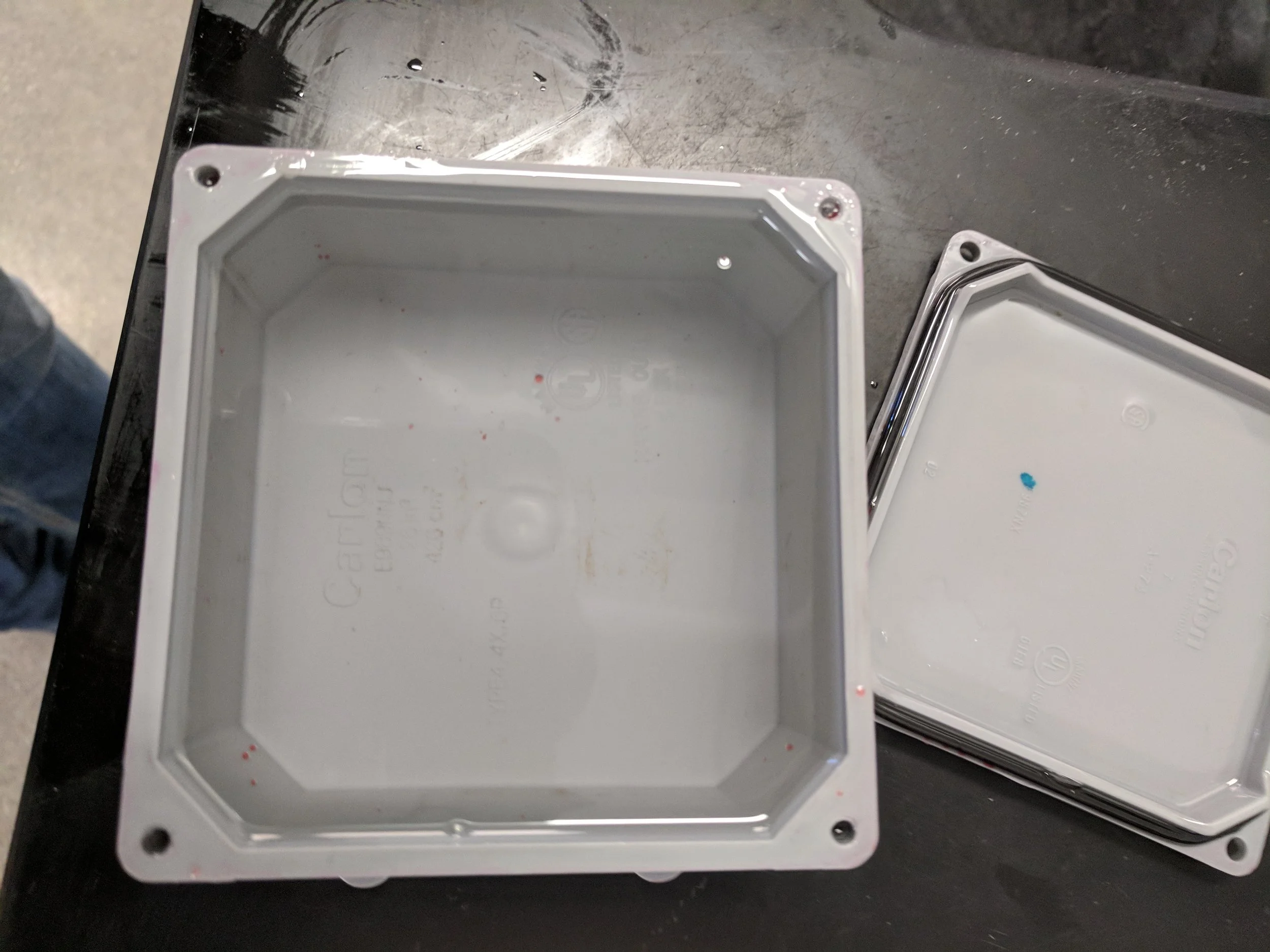
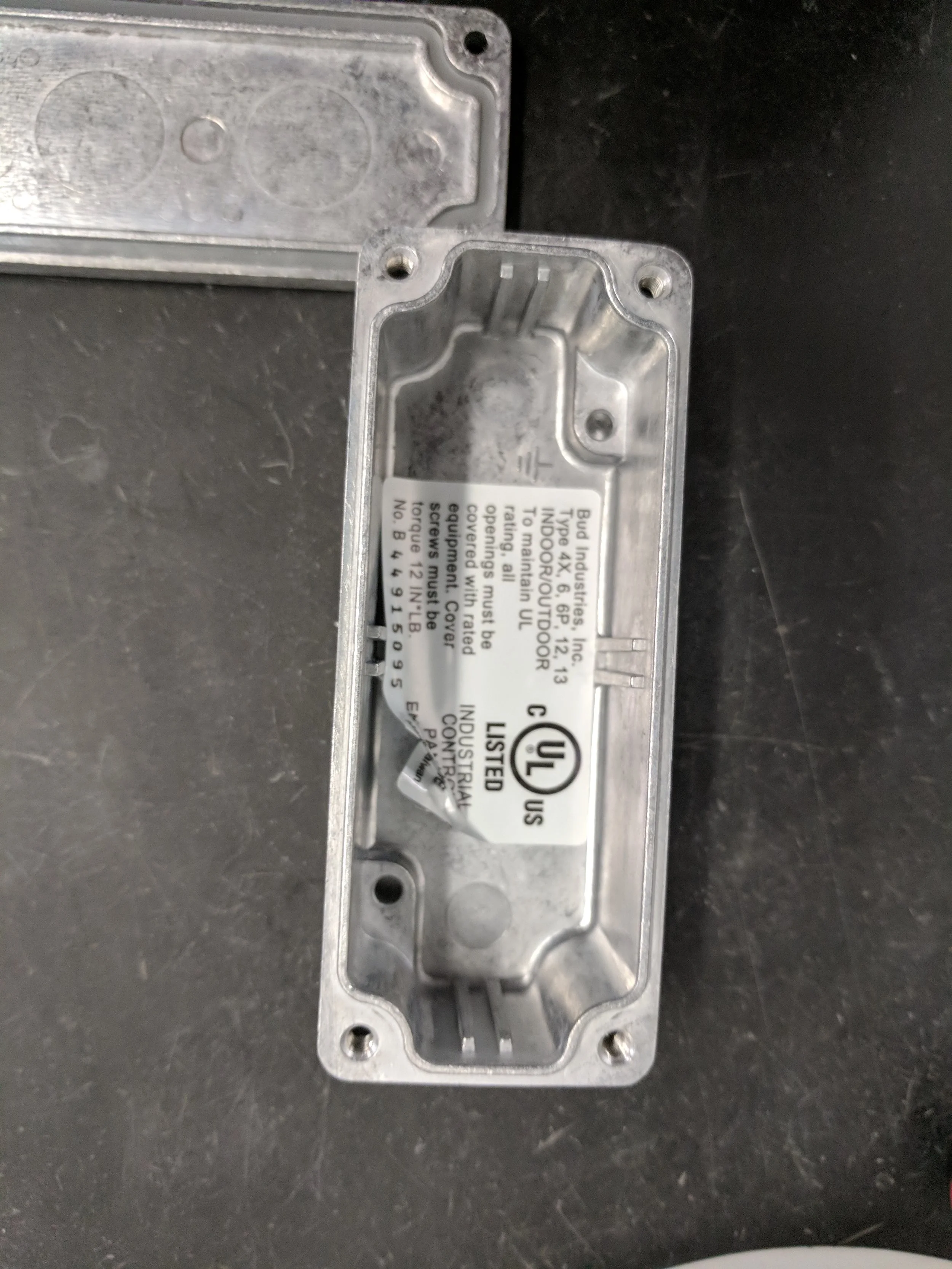
This is the box after being tested in the pressure chamber. As you can see, the inside is completely dry.
Next, shaft seals had to be manufactured. These seal designs were based off of industry standards released by Parker.
The shaft seals were machined and then epoxied into pipe nipple to allow for testing.
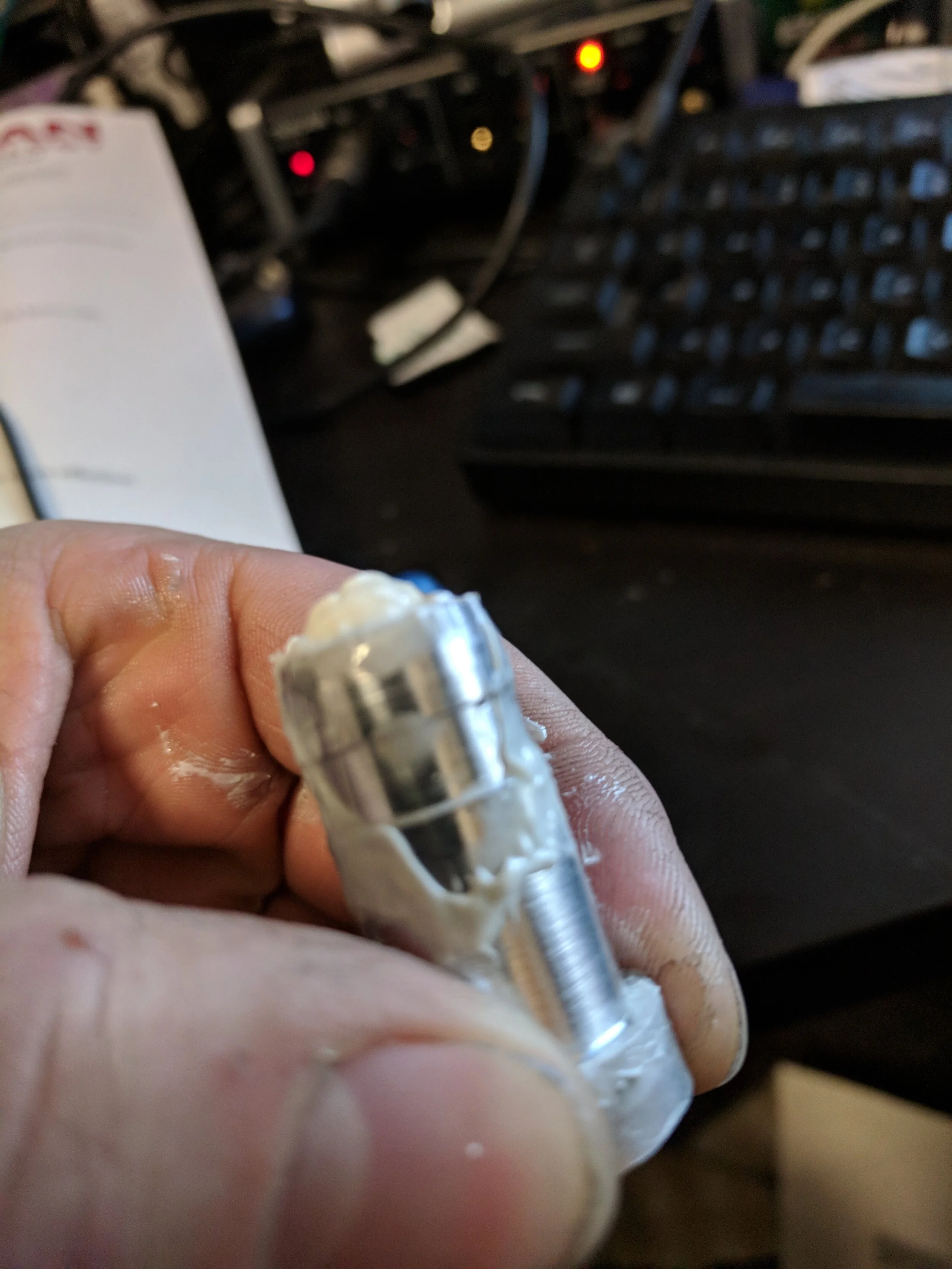
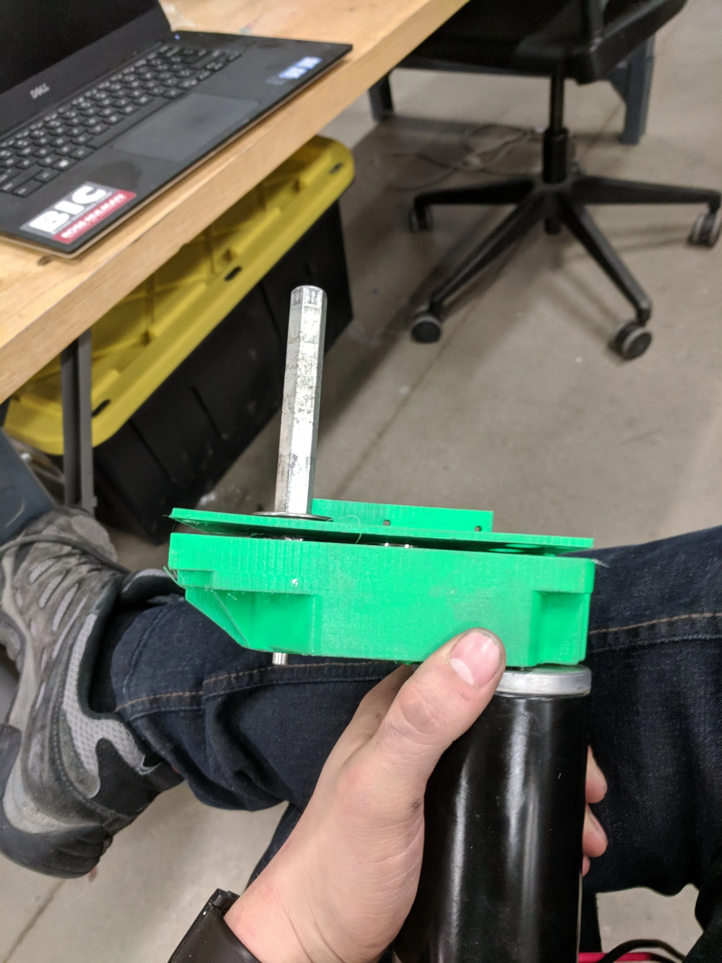
Pictured here is a prototype of the shaft geometry that would be used in the shaft seals.
An O ring would fit onto the grove and into a grove on the inside of the shaft seal.
After several attempts and geometries, this is the ammount of water that would leak into the pipe nipple with the shaft seal if it was filled with mineral oil.
Because of the running time, this leekage ammount seemed to be accemptable, so I moved forward, knowing that I would have to seal off the motor boxes from the control electronics later in the design,
On the mechanical side, I began disassembling the system so that it could be reassembled with the new drive system and water resistant hardware.
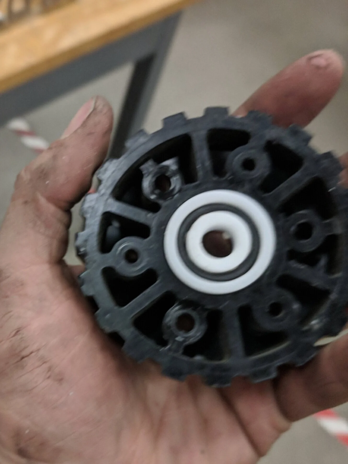
For the bearings in the pulley assembly, I chose to use plastic bearings because they would provide a lower rolling resistance than bushings while also not corroding in saltwater.
The previous system was far more powerful than was necessary, so new gearboxes were assembled using only two of the four total motors.
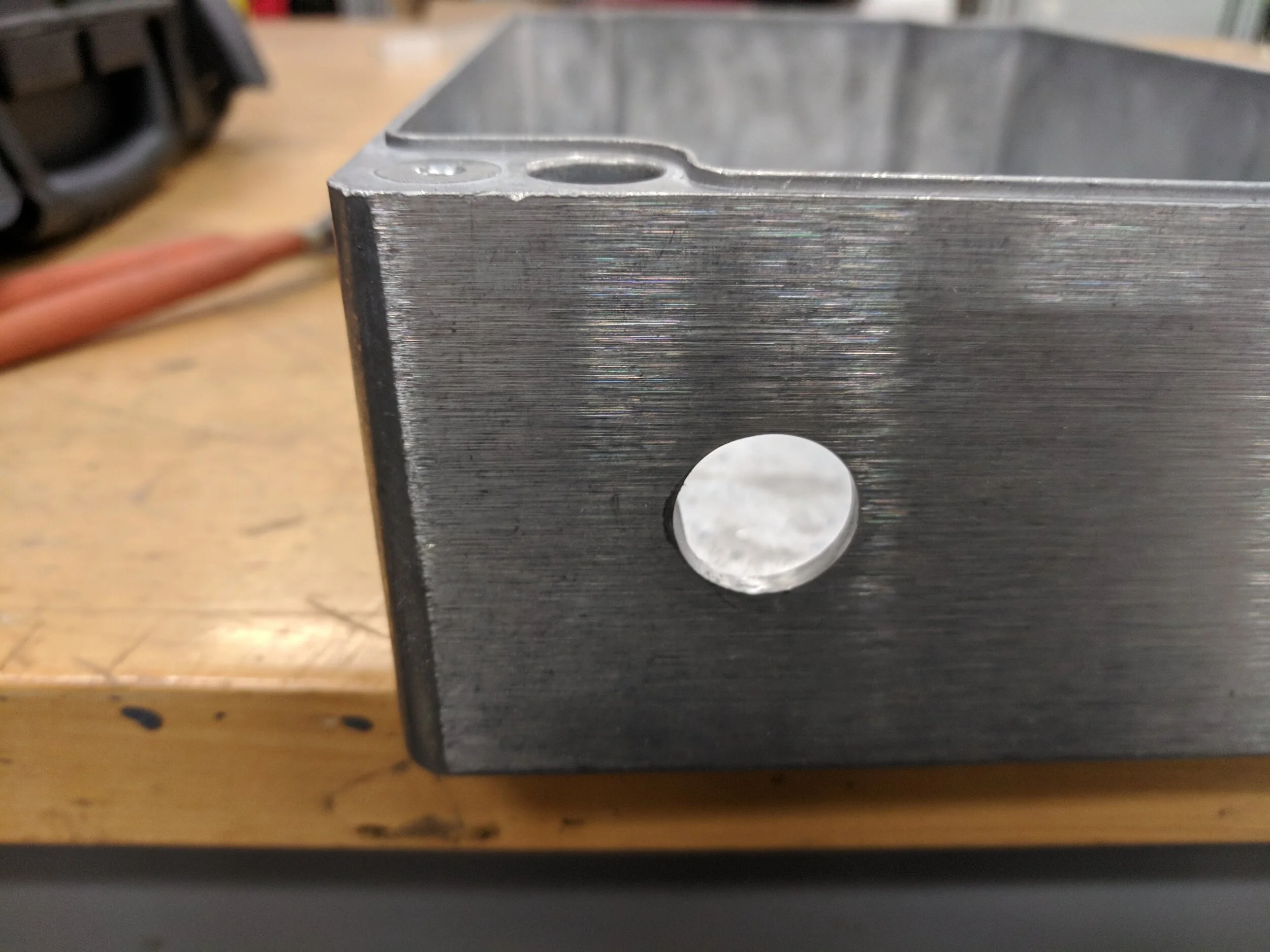
Once the Shaft seal geometry was set and the gearboxes made, the boxes were then drilled out to fit the shaft seal design.
Shaft seals were then put into the boxes and epoxied in.
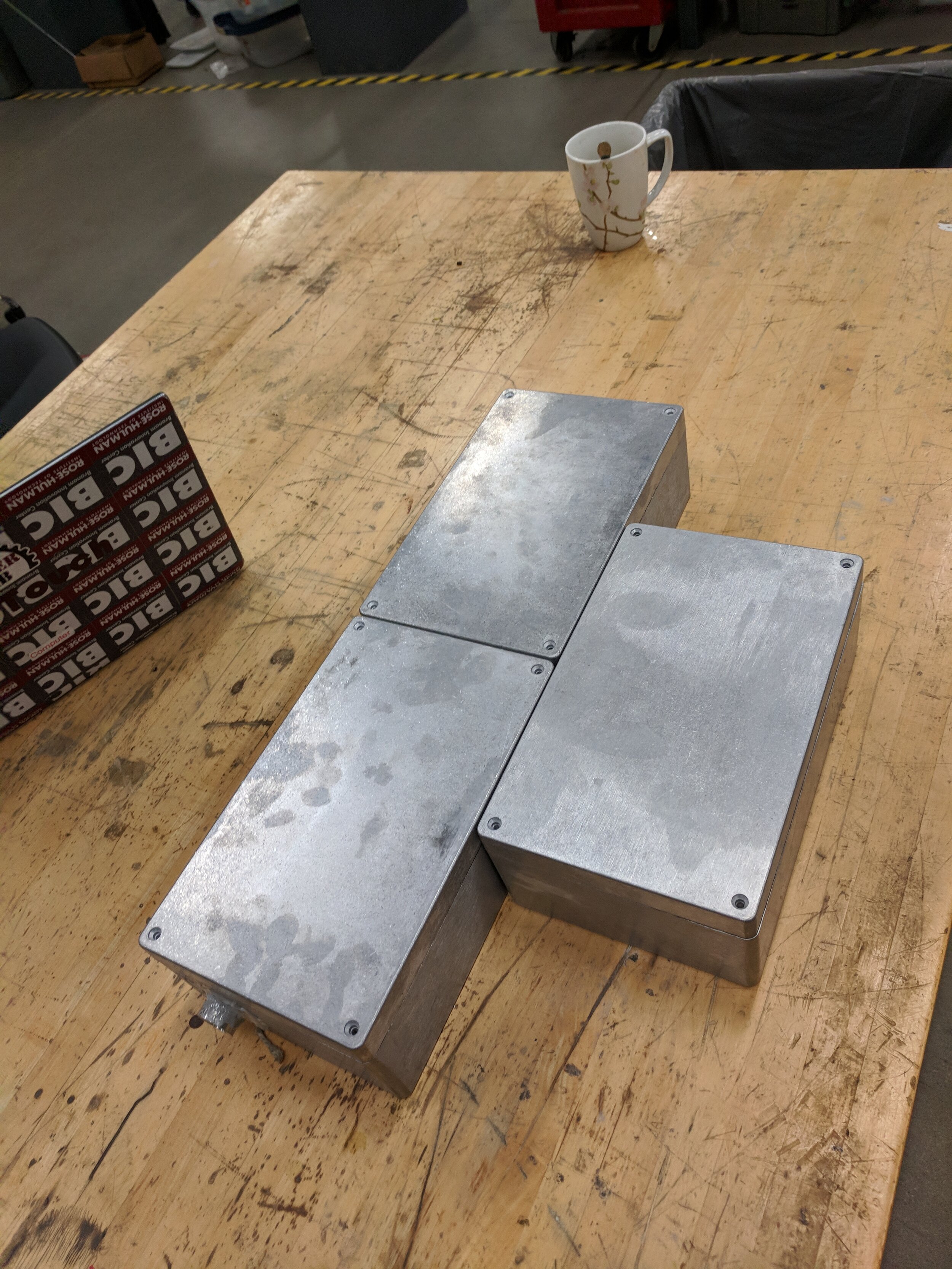
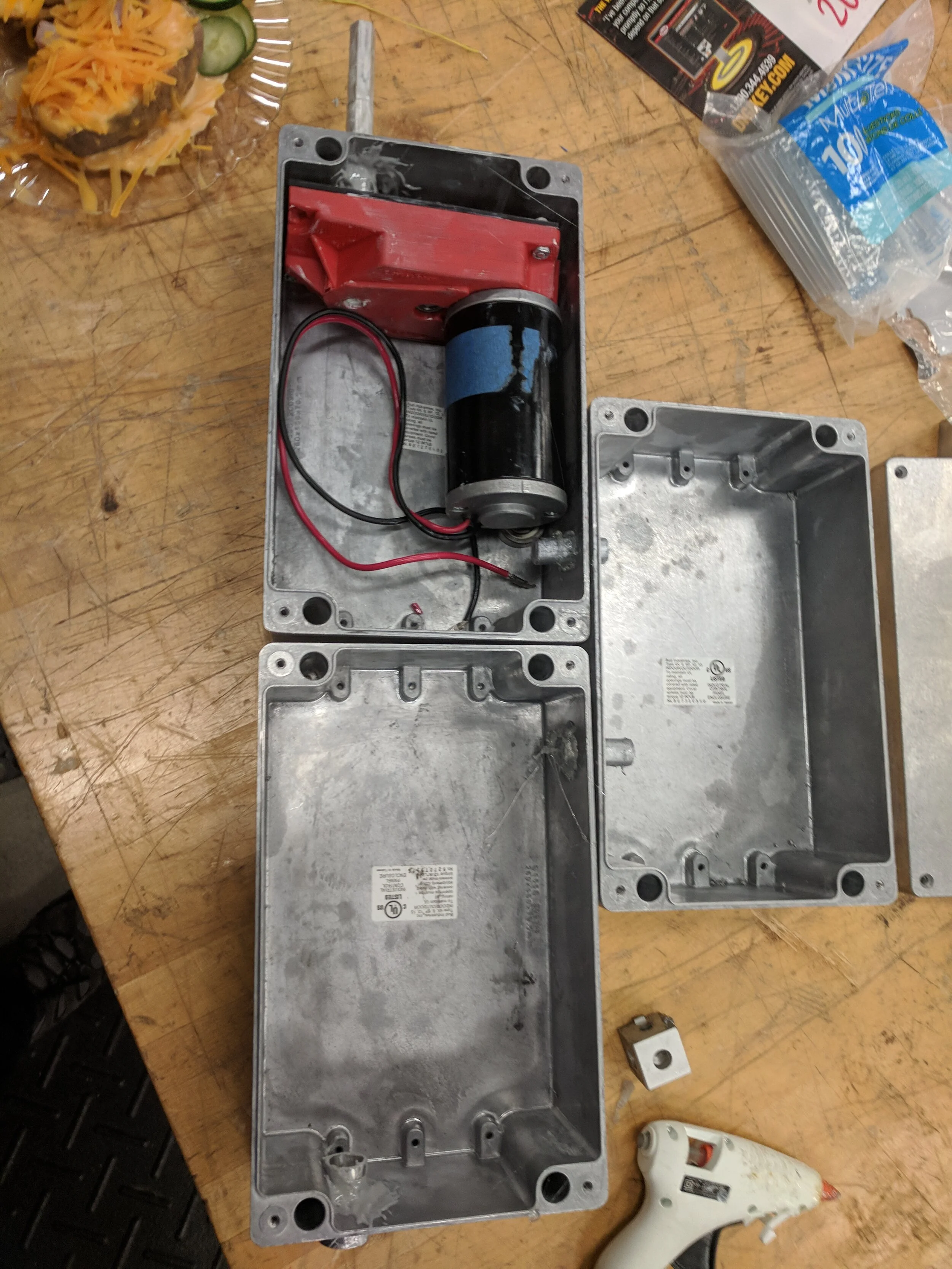
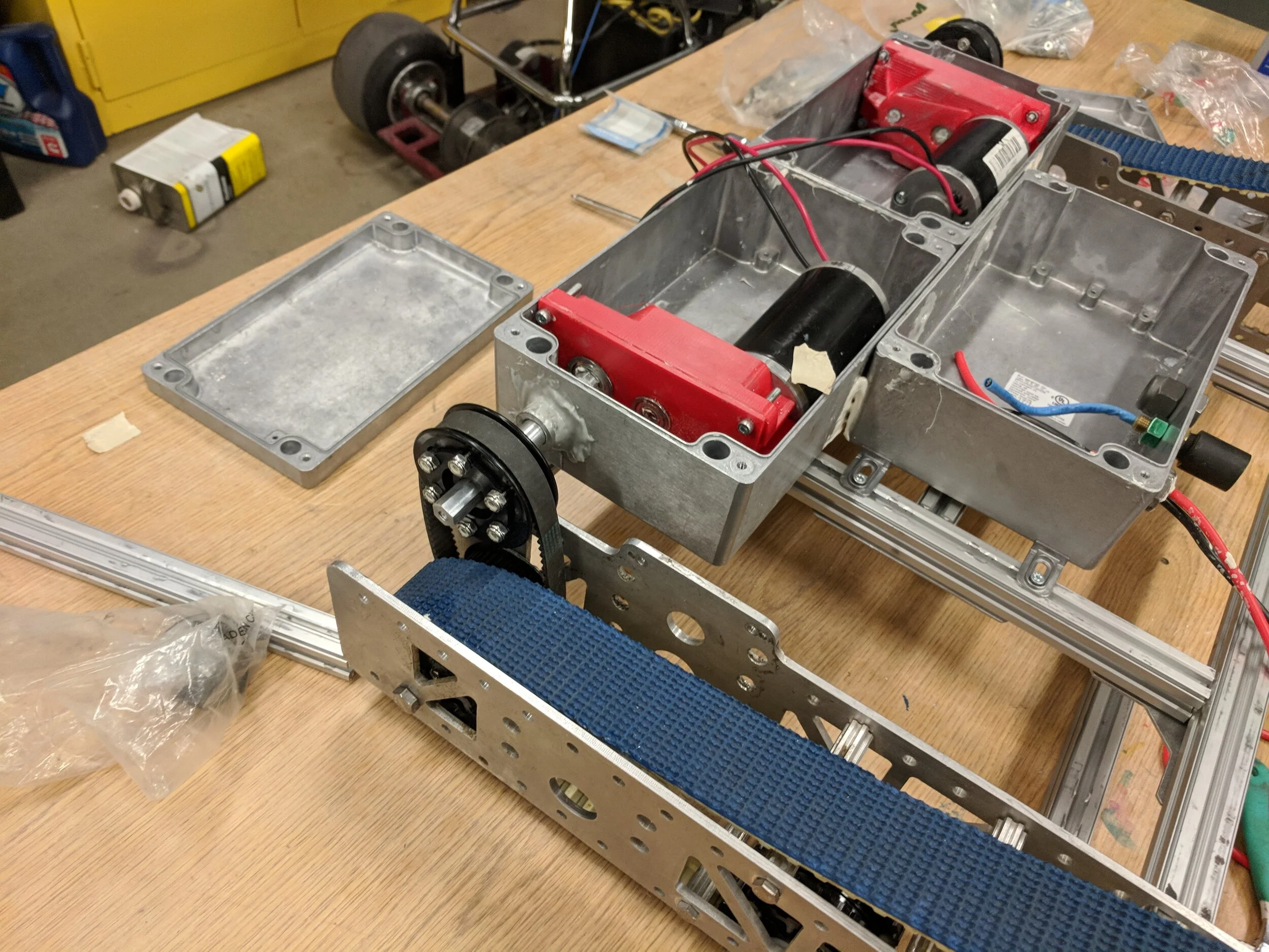
The final chosen enclosure arrangement is below. The rear two boxes contain the motor and gearbox assemblies while the front one has the control electronics.
For the data cable, the Underwater robotics team donated one of their older more problematic underwater connectors, which was more than good enough for the data transfer rates that would be necessary.
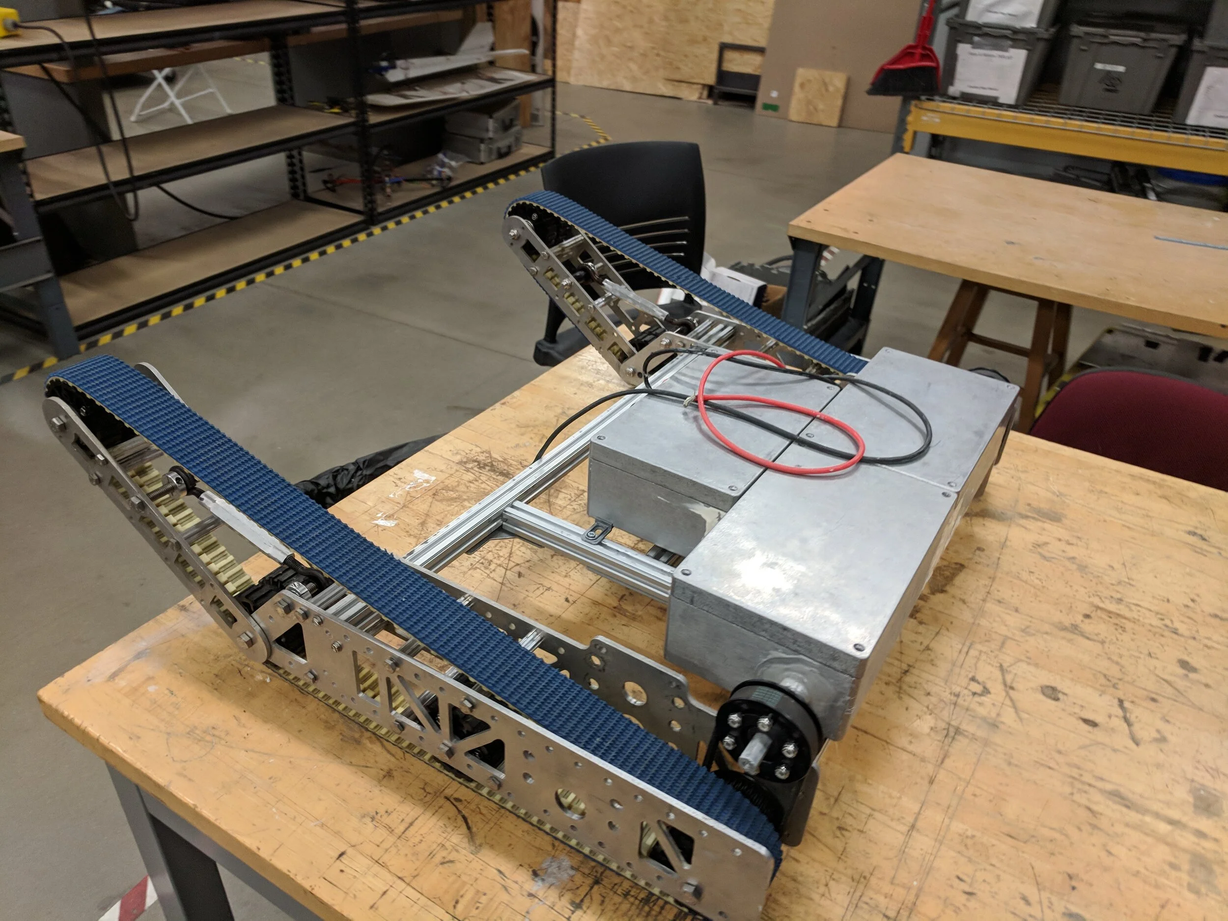
Here is a test fit of the enclosure assembly on the chassis with the treads attached.
Here is the final build of the first prototype.